Automation of Turn-out Switches in uST Complexes
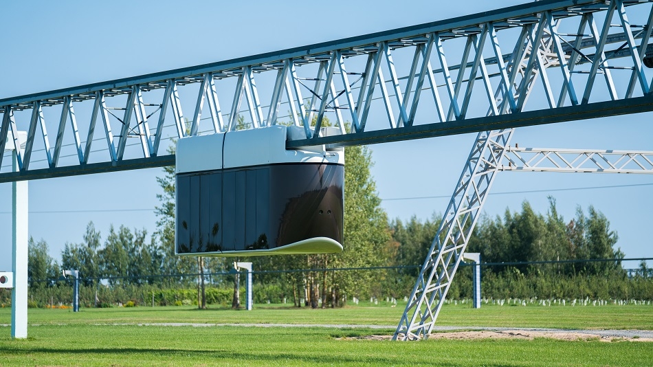
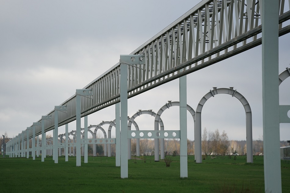
In modern transport systems, reliability and throughput largely depend on the efficiency of route branching. For uST complexes, this task is solved through automated turn-out switches. These are key elements of track infrastructure, responsible for smooth movement, turns, and changes in the direction of vehicles.
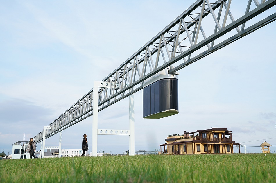
Turn-out switches in uST complexes are designed as high-precision mechatronic units integrated with the Automated Control System. Their purpose is not simply to mechanically direct rolling stock, but to ensure safe, fast, and fully controlled redistribution of transport flows.
Purpose of the Turn-out Switch
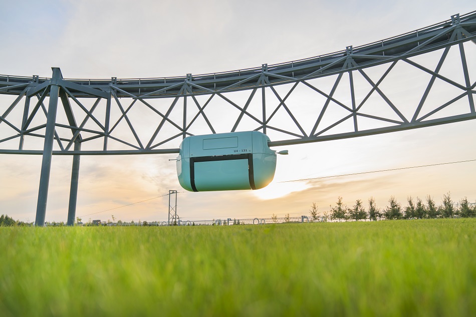
A turn-out switch is designed to route suspended or mounted vehicles: from a straight section of the track structure to a turning section and back; from the main branch to additional directions; for performing a turn or changing the direction of movement.
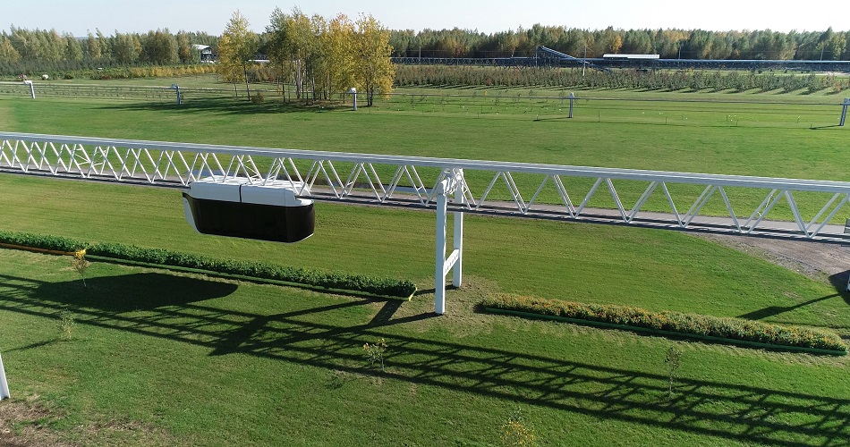
In uST complexes, turn-out switches function as part of a unified infrastructure framework, working synchronously with the Automated Control System, the vehicle positioning system, and the overall safety systems.
Principles of Automation
All types of turn-out switches in uST complexes operate in fully automatic mode. Control is centralized through the Automated Control System, which can determine the position of the vehicle (uPod), set the route, monitor the state of the switch, and block movement in case of any deviations from the norm.
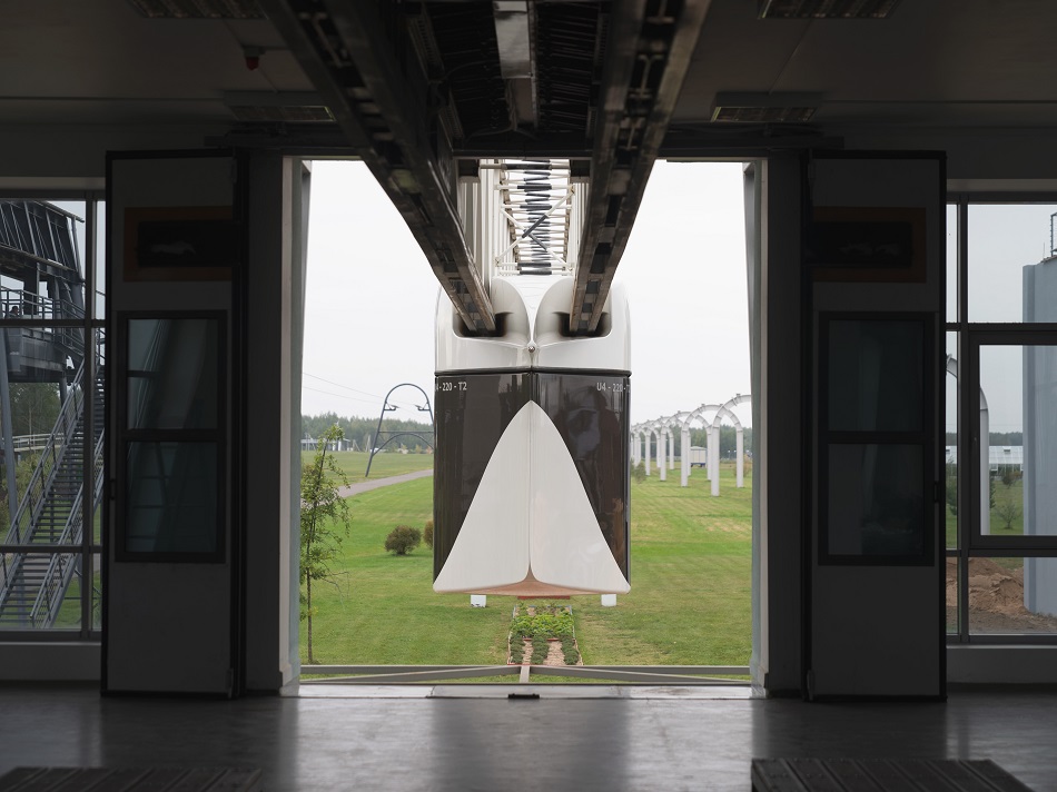
Before performing a maneuver, the system checks the readiness of all mechanisms and the correctness of the track structure’s position. Only after this is the uPod allowed to pass. It is important to note that turn-out switches come in several types and differ in their design.
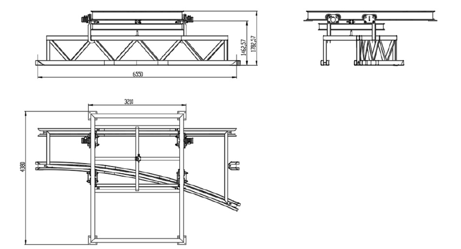
Lift-and-Slide Turn-out Switch
This is one of the most versatile design variants of this element. Its operating principle is based on two sequential operations. At the first stage, the frame of the turn-out switch is lifted vertically. This action is required to disengage the locking mechanisms and release the structure for movement.
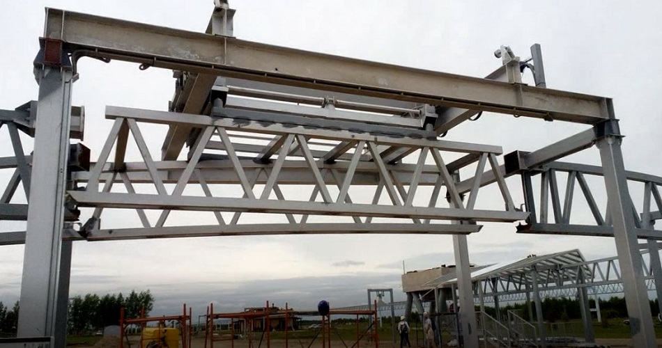
At the second stage, the frame is moved horizontally to the next branch of the track. After alignment with the required direction, the system automatically engages the locking mechanisms, ensuring rigid fixation of the switch in its operating position. This scheme guarantees high track alignment accuracy, reliable mechanical locking, as well as resistance to vibrations and loads generated by the rolling stock.
Sliding Turn-out Switch
The principle of this type of turn-out switch is simpler and based on horizontal movement of the frame into the required position, followed by mechanical locking. After the frame is shifted into place, fixing elements are activated, ensuring precise geometry of track junctions, rigid positioning, and structural stability during uPod passage.
Such switches are compact, feature high switching speed, and have a minimal number of moving parts, which simplifies maintenance and increases system lifespan.
Rotary Turn-out Switch (Turntable)
For organizing turns and connecting additional branches, a rotary-type turn-out switch – the turntable – is used. This engineering solution is especially effective at transport system hubs and terminal stations.
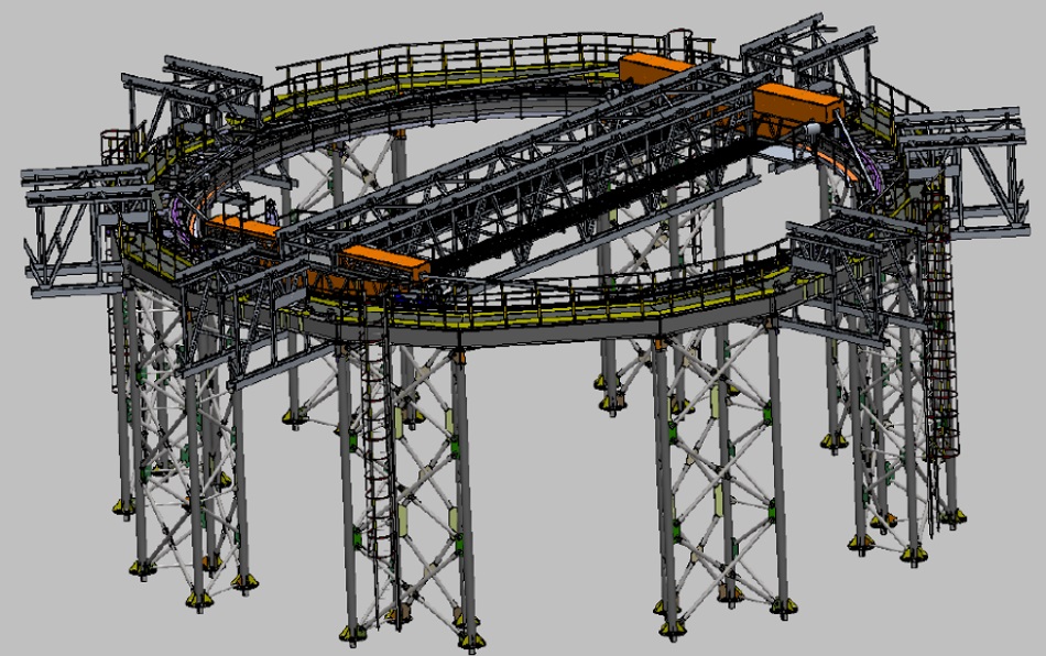
The operating principle of this type of switch consists of several stages. First, the vehicle enters the turntable and comes to a stop. Safety systems are then activated to hold the uPod in a fixed position.
Next, the turntable rotates around its axis until it aligns with the required track direction. After the rotation, the turntable is coupled with the track structure using additional locking elements. Finally, the system confirms route readiness and authorizes the vehicle to proceed.
This type of switch makes it possible to implement complex transport hubs without increasing the development footprint and without the need to construct additional turning loops.
Integration into the Automated Control System
The key difference between uST turn-out switches and classical railway solutions is full integration into the digital architecture of the transport complex. Each switch is equipped with:
- Position sensors;
- Locking mechanism control systems;
- Drives with redundancy;
- Communication channels with the Automated Control System.
This enables real-time monitoring of infrastructure status, remote diagnostics, and prevention of any abnormal situations.
Reliability as a Core Principle
Automation of turn-out switches in uST complexes is not just a technological solution but a component of systemic safety. The absence of manual control, multi-level protection, mechanical locking, and digital monitoring form an infrastructure capable of operating around the clock under any climatic conditions.
As a result, turn-out switches evolve from technically complex nodes into full-fledged tools for managing transport flows, ensuring route flexibility, high throughput, and predictable movement.
More news
News
26 January 2022
Through Tropical Rain: Unitsky String Technologies Inc. Continues Transport Testing
EcoTechnoPark. It's pouring rain. Unibus, crossing the territory of the innovation center, confidently overcomes the dense wall of rain. If a regular passenger bus driver were in a similar situation, they might have made a forced stop on the side of the road. But the unmanned uST transport continues to move calmly, as if nothing happens.
uLite
10 August 2023
The uLite: An Overview of the Complex Applications
What opportunities in the transportation industry can be offered by the first commercial project of UST Inc.?
uLite
20 November 2023
New generation transport: uLite as the best alternative to cable cars
There was no alternative to cable cars before the development of uLite transport and infrastructure complex.
